
Introduction to the Working Principle and Structure of the Raymond Mill
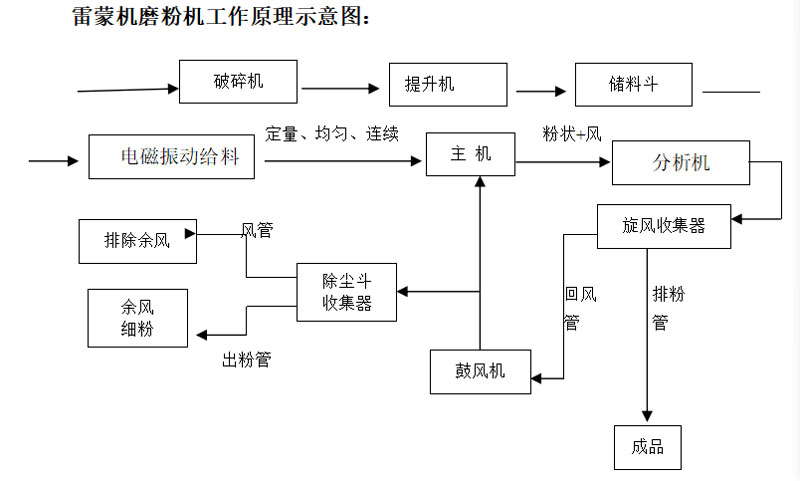
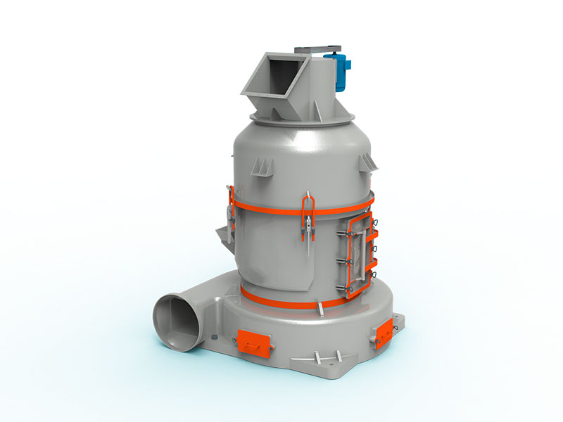
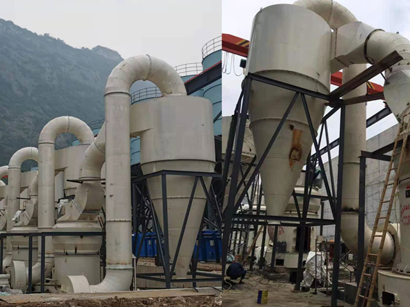
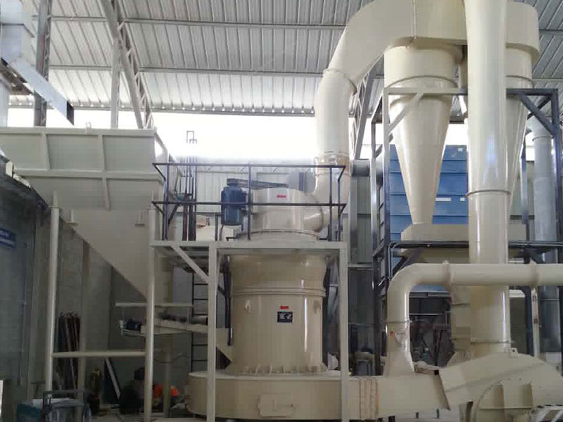
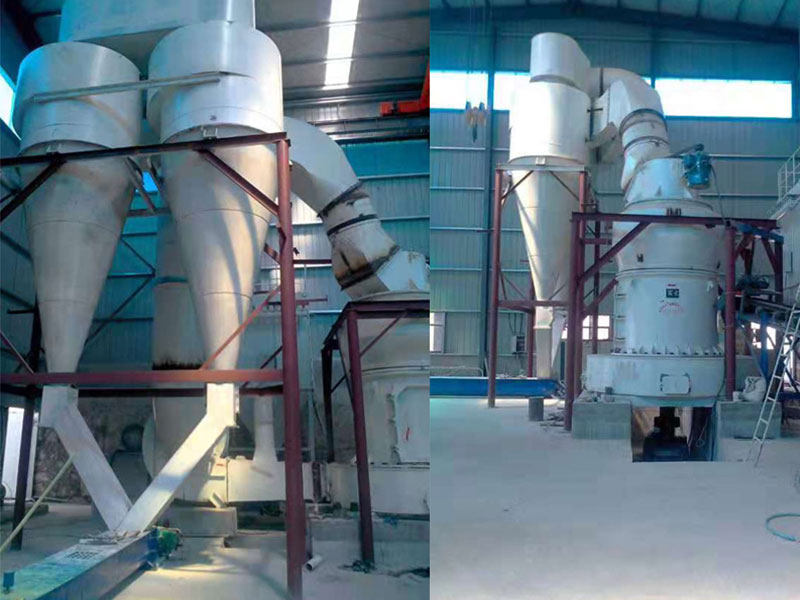
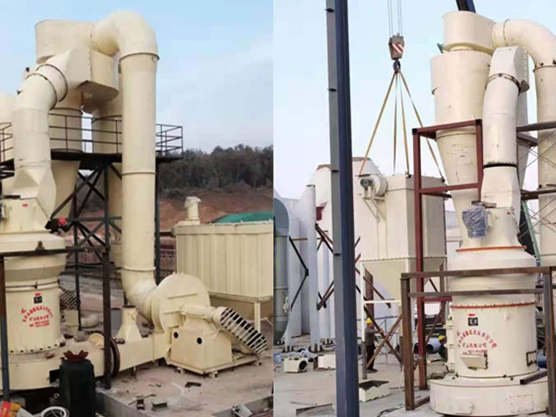
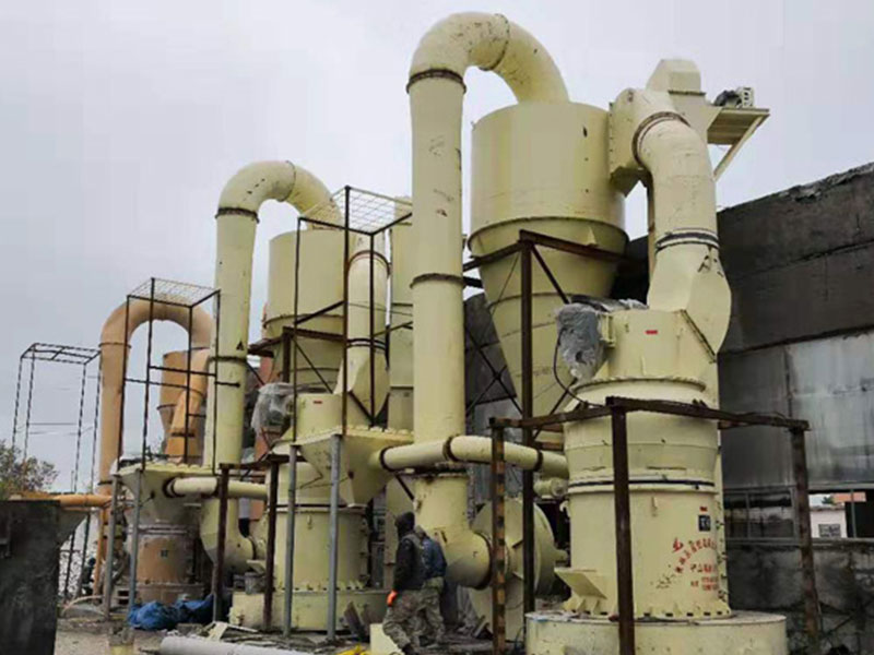
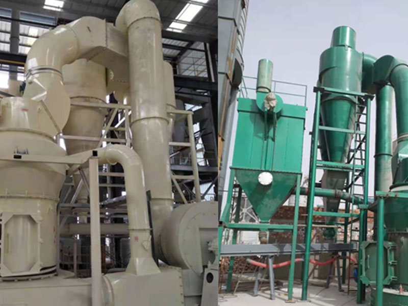
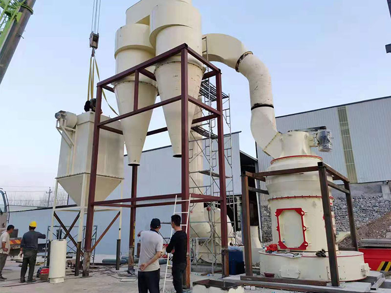
#### Working Principle This machine consists of a crusher, bucket elevator, storage hopper, electromagnetic vibrating feeder, blower, main unit, classifier, cyclone collector, piping system, dust collection hopper, electrical control cabinet, and other components (see the figure below).
After being crushed by the crusher into particles smaller than 20 mm, the material is lifted by the bucket elevator to the storage hopper, and then quantitatively, uniformly, and continuously fed by the electromagnetic vibrating feeder into the main chamber for grinding. Inside the main chamber, the grinding roller assembly supported on the plum-blossom frame rotates around the central shaft. Under the action of centrifugal force, the grinding rollers swing outward, thereby pressing tightly against the grinding ring, while at the same time rotating around their own roller shafts.
The crushed material is scooped up by the rotating shovel blade and thrown between the grinding rollers and the grinding ring, where it is crushed and ground by the rolling action of the grinding rollers. The ground powder is blown by the airflow from the blower to the classifier above the main unit for classification. Particles that are too coarse fall back into the main unit for regrinding, while particles meeting the required fineness enter the cyclone collector with the airflow. After collection, they are discharged through the powder outlet pipe and become the finished product (the finished product fineness can reach up to 600 mesh).
The purified airflow flows from the upper end of the cyclone collector through the pipe into the blower, and the air path is circulating. Except for the section from the blower to the grinding chamber, which is under positive pressure, the airflow in the remaining pipelines flows under negative pressure, resulting in better indoor sanitary conditions.
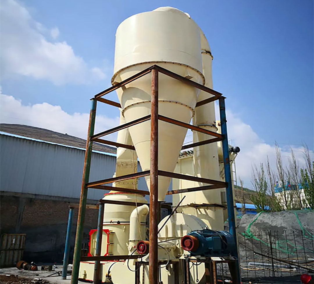
Since the moisture contained in the material evaporates into gas when heated during grinding, and gas leaking into the air duct from the flange joints of the pipelines and the feed inlet causes an increase in air volume in the circulating air path, this increased air volume is guided through the residual air pipe between the blower and the main unit into the dust collection hopper. Holes are opened on the upper end surface of the dust collection hopper, and a dust filter bag is suspended over each hole. When the residual airflow passes through the filter bags, the dust is collected by the bags and falls into the dust collection hopper for collection, while the purified gas is discharged into the atmosphere through the filter bags.
This article was published on May 22, 2026, and last updated on May 22, 2026. The article will be continuously updated.