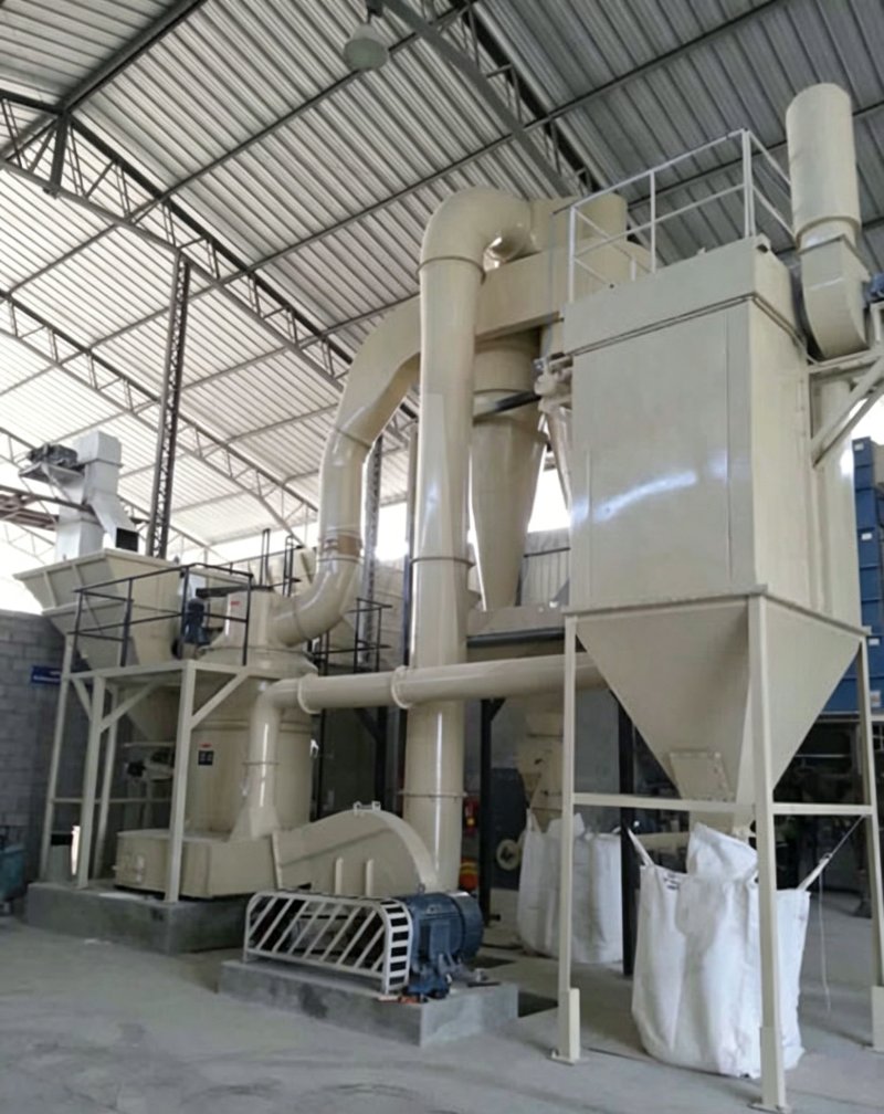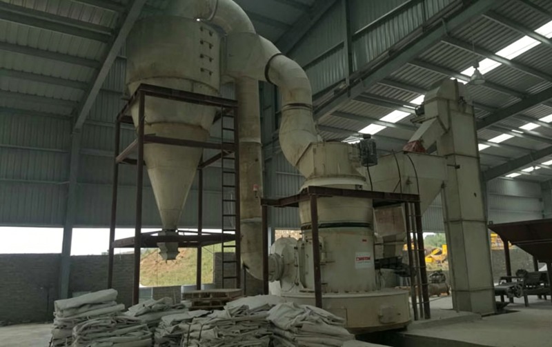
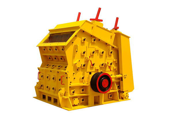
The impact crusher uses impact force to crush materials. It has a large crushing ratio and high crushing efficiency, so it is widely used in industrial sectors such as metallurgy, building materials, light industry, chemical industry, and electric power. The impact crusher has many parameters, and the various variables are interrelated and mutually restrictive, jointly affecting the machine’s performance. Therefore, mastering these rules, optimizing parameters and structure, and fully utilizing its characteristics and functions are of great significance for improving equipment productivity and product quality.
1. Rotor Diameter and Length
The rotor diameter of an impact crusher is generally related to the size of the feed material. When crushing materials, sufficient impact energy is required. In other words, the rotor diameter must have a certain size. If the rotor diameter is too small, the impact energy is insufficient and the material cannot be crushed; if the rotor diameter is too large, the energy consumption will be high, which is not favorable for energy saving.The relationship between rotor diameter and feed lump size can be determined according to the following empirical formula:
D = (2–4)d Where D is the rotor diameter, in mm; d is the maximum feed lump size, in mm. A larger value should be selected for small crushers, while a smaller value should be selected for large crushers. The rotor length is mainly determined according to the production capacity of the crusher. The ratio of rotor length L to diameter D is generally 0.5–1.2. When the L/D value is small, the structural stability of the machine body is poor, and this type of machine can only be used for single-rotor impact crushers with low material hardness and low handling capacity. However, if the L/D value is too large, the rigidity of the machine body will become poor.2. Number of Blow Bars
The more blow bars there are, the more impacts the rotor delivers per revolution, and the better the crushing effect. However, too many blow bars will make manufacturing more complicated and consume more materials. Generally, the number of blow bars is determined according to the rotor diameter. When the rotor diameter is relatively small, the number of blow bars is also small. Usually, when the rotor diameter is less than 1 m, 3 blow bars can be installed; when the rotor diameter is 1 m–1.5 m, 4–6 blow bars can be installed; when the rotor diameter is 1.5 m–2 m, 6–10 blow bars can be installed. When the material is hard and the crushing ratio is large, the number of blow bars can be increased.3. Inclination Angle of the Feed Guide Plate
In an impact crusher, the material enters the crushing chamber along the guide plate, so the guide plate inclination angle β is an important parameter. The smaller the β angle, the slower the material slides down along the guide plate, allowing the material to be crushed more fully and resulting in better product quality. However, if the inclination angle β is too small, it will affect productivity and may even cause material accumulation. The larger the inclination angle, the faster the material slides down along the guide plate, which is beneficial to improving crushing efficiency. But if it is too large, the material will not be crushed sufficiently, affecting product quality. In addition, a larger inclination angle increases the height of the crusher. The inclination angle is generally between 45° and 60°. When other conditions permit, it is advisable to choose a smaller inclination angle. When selecting the guide plate inclination angle, the relationship between the material sliding off the guide plate and meeting the blow bar should also be considered. If the material slides off the guide plate (leaves the discharge point) before the blow bar arrives (blow bar lag phenomenon), or if the material has not yet slid off the guide plate when the blow bar just reaches the position but still does not meet the material (blow bar lead phenomenon), the crushing effect will be poor. It is best for the material to slide off the guide plate and meet the blow bar simultaneously, as this gives the best crushing effect.4. Guide Plate Discharge Point
The position of the guide plate discharge point is described by the angle a between the line connecting the guide plate discharge point to the rotor center and the horizontal line passing through the rotor center. A smaller angle a means the crusher height is relatively lower, which can reduce the machine height and weight. For mobile crushers, reducing height is very beneficial. In addition, a smaller angle a can increase the arc length of the crushing chamber. However, if a is too small, the impact force will be insufficient, causing the material particle size to fail to meet process requirements, and excessively large material may easily cause blockage inside the machine. Therefore, the value of a should be determined reasonably. When other conditions permit, a smaller a is preferable; generally, a ≤ 30° is considered more appropriate.5. Suspension Position of the Impact Plate
There are many parameters for the suspension position of the impact plate, and they have the greatest influence on the performance of the crusher (taking the suspension position of the first-stage impact plate in a two-stage impact plate as an example). The suspension position parameters of the first-stage impact plate include x, y, δ, θ, and △.Structural Dimensions of the Impact Crusher
x and y represent the starting point position of the first section of the first-stage impact plate. If x and y are too large, the material travels a longer distance, and the speed and momentum of the material striking the plate surface decrease due to resistance, resulting in a poor crushing effect. If x and y are too small, the material acceleration time is short, and it strikes the plate surface before reaching maximum speed and momentum, which is also unfavorable for crushing. Therefore, x and y should be selected reasonably according to the crusher rotor diameter D, the feed guide plate inclination angle β, and the striking angle α. Generally: x = (0.15–0.35)D y = (0.70–1.20)D For larger α and β values, relatively larger values should be selected; for smaller α and β values, relatively smaller values should be selected; for larger crushing particle size and higher material hardness, larger values should be selected. δ is the angle between the tangent line of the outer circle of the blow bar and the normal line of the impact plate, that is, the angle between the movement direction of the material striking the impact plate and the normal line of the impact plate. According to collision theory, when the material collides with the impact plate along the normal line to the impact plate surface, that is, in a direct collision, the force is the greatest, the crushing effect is better, and liner wear is also less. Therefore, δ should be 0°. To ensure that when the rotor moves to different positions, the material always strikes the impact plate perpendicularly, the impact plate curve should ideally be an involute. However, involute curves are difficult to manufacture, so impact plates are often replaced by two forms: broken lines and arc lines. Therefore, for non-involute impact plates, in order to make the impacts at different positions approximate direct collision, δ is generally 1–2°.6. Rotor Speed
Rotor speed is one of the important working parameters of the impact crusher. It plays a decisive role in the crusher’s production capacity, product particle size, and crushing ratio. Tests have shown that as rotor speed increases, both production capacity and crushing ratio increase significantly, and the product particle size becomes finer. However, as rotor speed increases, power consumption also increases, blow bar wear accelerates, and the requirements for the machine’s manufacturing precision also rise accordingly. For coarse crushing, the rotor circumferential linear speed is often taken as v = 15 m/s–40 m/s; for fine crushing, v = 40 m/s–80 m/s. After determining the rotor circumferential linear speed, the rotor speed is: n = 60 × 1000v / (πD) Where n is the rotor speed, in r/min; D is the rotor diameter, in mm.7. Productivity
The productivity of the impact crusher is related to the rotor speed and geometric parameters. Among all the parameters of the impact crusher, the suspension position of the impact plate has the greatest influence on crusher performance. After the equipment model is selected, other parameters are already determined, and only the suspension parameters of the impact plate remain adjustable. During production, they should be adjusted at any time according to the actual situation so as to bring the machine to its optimal working condition. Rotor imbalance and severe wear of the impact plate hammer are common problems of impact crushers. Selecting suitable blow bar materials and structures, and carrying out necessary balancing and balance correction, are the keys to solving these problems. During equipment operation, correct operation and maintenance of the equipment, close attention to the rotor’s running condition, and timely handling of problems when discovered are also effective measures to improve the performance of the impact crusher.This article was published on May 22, 2026, and last updated on May 22, 2026. The article will be continuously updated.